SiC MOSFET
SiC MOSFET原理上在開關過程中不會產生拖尾電流,可高速運行且開關損耗低。低導通電阻和小型晶片尺寸造就較低的電容和閘極電荷。此外,SiC還具有如導通電阻增加量很小的優異的材料屬性,並且有比導通電阻可能隨著溫度的升高而上升2倍以上的矽(Si)器件更優異的封裝微型化和節能的優點。
第4代SiC MOSFET
新推出的第4代SiC MOSFET,在改進短路耐受時間的前提下,實現了業界超低導通電阻。另外,還具有低開關損耗和支援15V閘-源電壓等特性,有助設備進一步實現節能化。
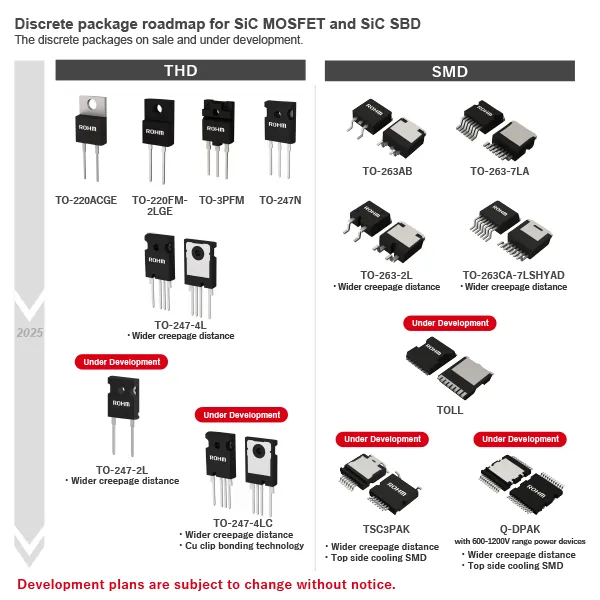
SiC MOSFET、SiC SBD離散式封裝規劃進程
現有的封裝產品陣容以及正在開發的封裝。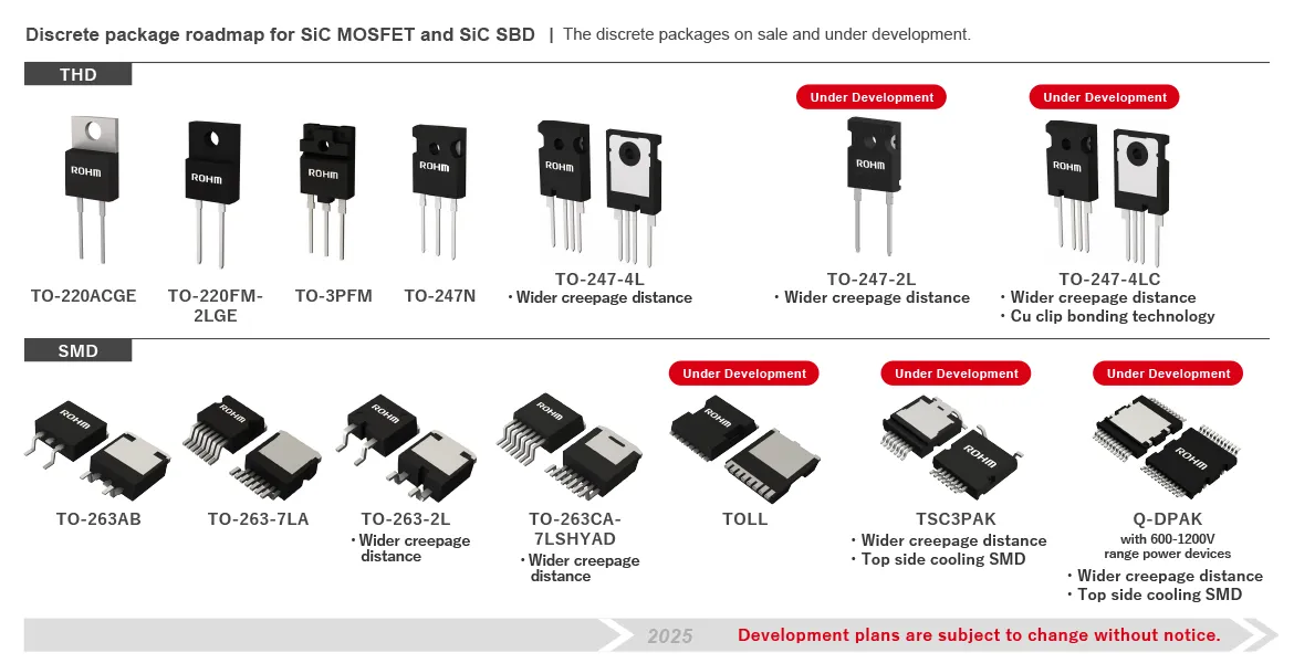
Easy Part Finder
Parametric Search
Supporting Information
第4代SiC MOSFET
ROHM量產中的第4代SiC MOSFET,是在改進短路耐受時間的情況下實現業界超低導通電阻的產品,目前不僅可供應裸晶片,還可供應Discrete封裝形式的產品。
特點
1.改進短路耐受時間,實現業界頂級低導通電阻
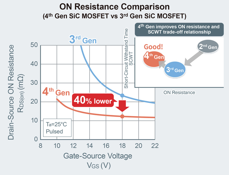
在第4代SiC MOSFET中,透過進一步改進ROHM自有雙溝槽結構,成功改善了主驅逆變器所要求的短路耐受時間,使導通電阻比傳統產品降低約40%,實現了業界頂級低導通電阻。
2.透過大幅降低寄生電容,實現更低開關損耗
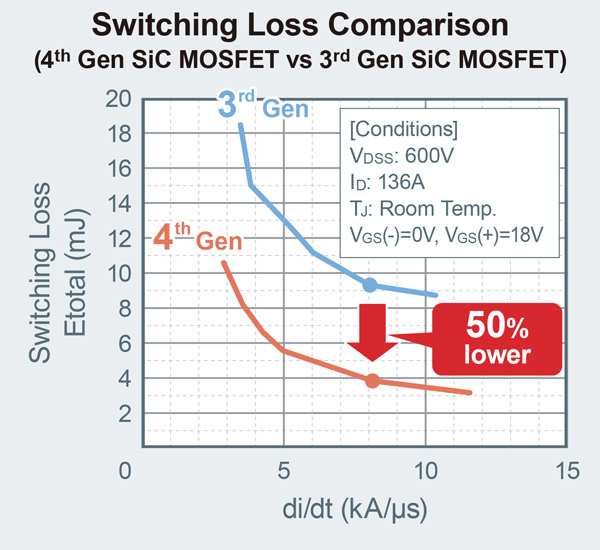
第4代SiC MOSFET透過大幅降低閘極-汲極間電容(Cgd),成功使開關損耗比傳統產品降低約50%。
3.支援15V閘極-源極電壓,簡化應用產品設計
在MOSFET中,需要在元件ON時向電晶體的閘極施加一定量的電壓。除了到第3代SiC MOSFET為止所支援的18V閘極-源極電壓(Vgs)外,第4代SiC MOSFET還支援更容易處理的15V閘極-源極電壓,可與IGBT一起用來設計驅動電路(閘極驅動電路)。
應用範例:主驅逆變器
有助於包括車載逆變器和各種開關電源在內,各種應用產品實現顯著的小型化和更低功耗,比如在用於車載主驅逆變器時,與使用IGBT時相比,效率可以得到顯著提升,主要體現在逆變器的高扭矩和低轉速範圍,從而可使電耗減少6%(按國際標準“WLTC燃料消耗量測試”計算)。
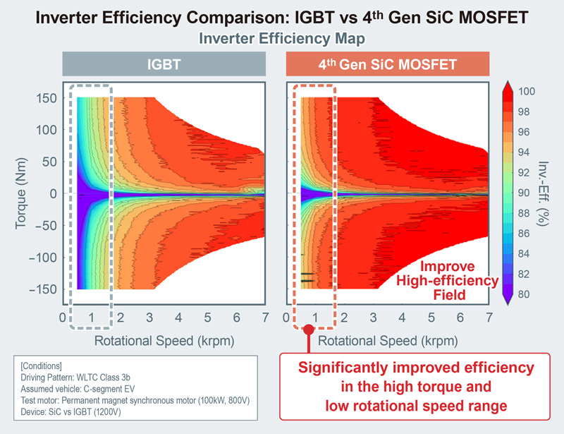
第4代SiC MOSFET 支援資訊
評估板
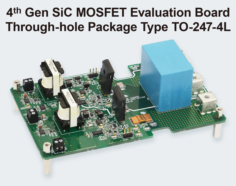
4th Generation SiC MOSFET Half Bridge Evaluation Board
P04SCT4018KE-EVK-001/P05SCT4018KR-EVK-001
P04SCT4018KE-EVK-001/P05SCT4018KR-EVK-001是一款可評估採用TO-247N/TO-247-4L封裝的第4代SiC MOSFET的評估板。對於所搭載的SiC MOSFET,可以選擇並購買所需導通阻值的元件來進行評估。該評估板中配有閘極驅動器和週邊電路,可有效減少設計和評估工時。
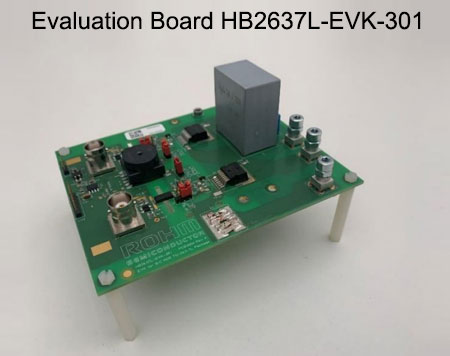
Evaluation Board HB2637L-EVK-301
The evaluation board is configured in a half bridge set up and thus allows evaluations in different operations modes such as buck, boost, synchronous buck/boost and inverter operations. The board is equipped with two SiC MOSFETs(SCT4036KW7), isolated gate driver BM61S41RFV-C, isolated power supply required for the gate driver, LDO for 5V supply and easy to interface connectors for PWM signals.
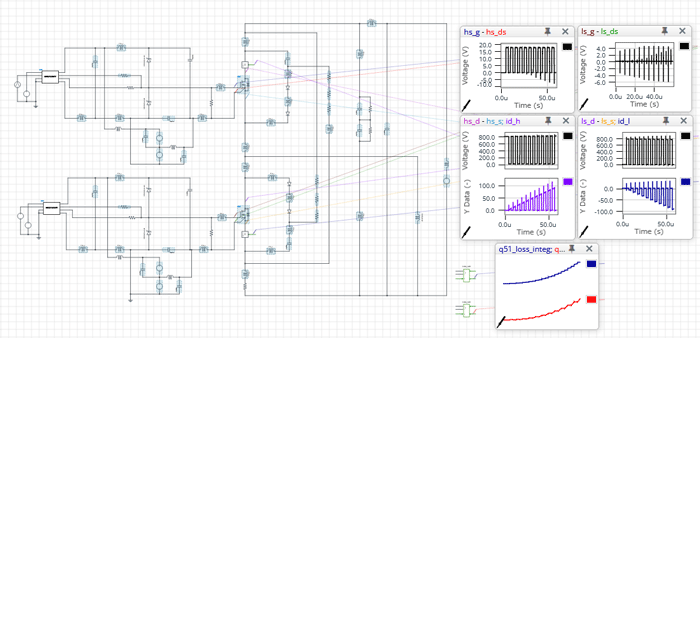
EVK Simulatrion (ROHM Solution Simulator)
・P05CT4018KR-EVK-001 Double Pulse Test
・P04SCT4018KE-EVK-001 Double Pulse Test
・HB2637L-EVK-301 Double Pulse Test
我們對評估板進行了建模作業,並在線上模擬器中為第4代SiC MOSFET準備了雙脈衝測試環境。 可以透過模擬評估工作電壓、柵極驅動電路、緩衝電路常數等引起的開關波形,並有助於減少實機評估的工時,以及用於對寄生電感的效果評估等。(需要註冊MyROHM)。
Documents
White Paper
Application Note
- 4th Gen SiC MOSFETs Discrete Package:Characteristics and Precautions for Circuit Design Application Note
- 5kW Inverter Circuit Using 4th Generation SiC MOSFETs
- Application Benefits of Using 4th Generation SiC MOSFETs
Design Model
| Part Number | Drain-source Voltage[V] | Drain-source On-state Resistance (Typ.(mΩ) |
Package | SPICE Model? |
PLECS Model? |
PSIM Model? |
PCB Library? |
| SCT4045DE | 750 | 45 | TO-247N |
||||
| SCT4026DE | 26 | ||||||
| SCT4013DE | 13 | ||||||
| SCT4062KE | 1200 | 62 | |||||
| SCT4036KE | 36 | ||||||
| SCT4018KE | 18 | ||||||
| SCT4045DR | 750 | 45 | TO-247-4L |
||||
| SCT4026DR | 26 | ||||||
| SCT4013DR | 13 | ||||||
| SCT4062KR | 1200 | 62 | |||||
| SCT4036KR | 36 | ||||||
| SCT4018KR | 18 | ||||||
| SCT4045DW7 | 750 | 45 | TO-263-7L |
||||
| SCT4026DW7 | 26 | ||||||
| SCT4013DW7 | 13 | ||||||
| SCT4062KW7 | 1200 | 62 | |||||
| SCT4036KW7 | 36 | ||||||
| SCT4018KW7 | 18 |
Simulations (Login Required)
- [4th Gen SiC] D-001. P05SCT4018KR-EVK-001 Double Pulse Test
- [4th Gen SiC] D-002. P04SCT4018KE-EVK-001 Double Pulse Test
- [4th Gen SiC] D-003. HB2637L-EVK-301_SCT4036KW7 Double Pulse Test
TO-247N (3pin)
- [4th Gen SiC] A-011b. Totem-pole PFC Vin=220V Vout=400V Pout=3.3kW
- [4th Gen SiC] C-016b. LLC Full-Bridge Vin=400V Vout=500V Pout=3.3kW
TO-247-4L (4pin)
SiC MOSFET 支援資訊
評估板
| Category | SiC Product | Image | Part No. | User Guide | Purchase Board |
|
| SiC-MOS | Evaluation Board |
SCT4XXX series Trench(4th Generation) TO-247-N | 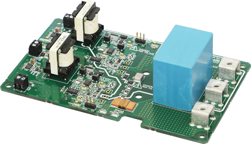 |
NEW P04SCT4018KE-EVK-001 |
User Guide Product Specification |
Online Distributors |
| SCT4XXX series Trench(4th Generation) TO-247-4L | 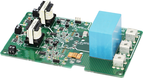 |
NEW P05SCT4018KR-EVK-001 |
Online Distributors |
|||
| SCT3XXX series Trench(3rd Generation) TO-247-4L |  |
P02SCT3040KR-EVK-001 | User Guide Product Specification |
Online Distributors |
||
Documents
White Paper
- 4 Steps for Successful Thermal Designing of Power Devices
- Cutting-Edge Web Simulation Tool “ROHM Solution Simulator” Capable of Complete Circuit Verification of Power Devices and Driver ICs
- The Problem with Traditional Vaccine Storage Freezers and How ROHM Cutting-edge Power Solutions Can Take them to the Next Level
- LEADRIVE: Design, Test And System Evaluation Of Silicon Carbide Power Modules And Motor Control Units
- Solving The Challenges Of Driving SiC MOSFETs With New Packaging Developments
Application Note
- 4th Gen SiC MOSFETs Discrete Package:Characteristics and Precautions for Circuit Design Application Note
- 5kW Inverter Circuit Using 4th Generation SiC MOSFETs
- Application Benefits of Using 4th Generation SiC MOSFETs
- 5kW High-Efficiency Fan-less Inverter
- 800V Three-Phase Output LLC DC/DC Resonant Converter
- Improvement Of Switching Loss By Driver Source
- Basics and Design Guidelines for Gate Drive Circuits
Technical Articles
Schematic Design & Verification
- Oscillation countermeasures for MOSFETs in parallel
- Application Note for SiC Power Devices and Modules
- Calculating Power Loss from Measured Waveforms
- Calculation of Power Dissipation in Switching Circuit
- Method for Monitoring Switching Waveform
- Precautions during gate-source voltage measurement for SiC MOSFET
- Snubber circuit design methods for SiC MOSFET
- Gate-source voltage behaviour in a bridge configuration
- Gate-Source Voltage Surge Suppression Methods
- Importance of Probe Calibration When Measuring Power: Deskew
- Impedance Characteristics of Bypass Capacitor
- Basics and Design Guidelines for Gate Drive Circuits
- SiC MOSFET Layout Design Considerations
- Best practices for the connection of Driver Source/Emitter terminals in discrete devices
Thermal Design
- What Is Thermal Design
- Basics of Thermal Resistance and Heat Dissipation
- Method for Calculating Junction Temperature from Transient Thermal Resistance Data
- Notes for Temperature Measurement Using Thermocouples
- Two-Resistor Model for Thermal Simulation
- Notes for Temperature Measurement Using Forward Voltage of PN Junction
- What is a Thermal Model? (SiC Power Device)
- How to Use Thermal Models
- Measurement Method and Usage of Thermal Resistance RthJC
- Precautions When Measuring the Rear of the Package with a Thermocouple
Models & Tools
Simulations (Login Required)
「ROHM Solution Simulator」是一款能在ROHM官網上運行的電子電路模擬工具。從零件選擇和元件單體驗證等研發初期階段到系統級的驗證階段,各項模擬工作都可以在Web上執行。ROHM提供的SiC元件等功率元件產品、驅動IC和電源IC等IC產品,都可以在接近實際環境的解決方案電路中輕易地進行驗證,大幅縮短研發週期。
TO-247N (3pin)
- [4th Gen SiC] A-011b. Totem-pole PFC Vin=220V Vout=400V Pout=3.3kW
- [4th Gen SiC] C-016b. LLC Full-Bridge Vin=400V Vout=500V Pout=3.3kW
TO-247-4L (4pin)
- [4th Gen SiC] A-011a. Totem-pole PFC Vin=220V Vout=400V Pout=3.3kW
- [4th Gen SiC] C-016a. LLC Full-Bridge Vin=400V Vout=500V Pout=3.3kW
- [4th Gen SiC] D-001. P05SCT4018KR-EVK-001 Double Pulse Test
- [4th Gen SiC] D-002. P04SCT4018KE-EVK-001 Double Pulse Test
- [4th Gen SiC] D-003. HB2637L-EVK-301_SCT4036KW7 Double Pulse Test
- A-001. Boost PFC VIN=200V, IIN=2.5A BCM
- A-002. Boost PFC VIN=200V, IIN=2.5A CCM
- A-003. Boost PFC VIN=200V, IIN=2.5A CCM Synchronous FETs
- A-004. Boost PFC VIN=200V, IIN=2.5A DCM
- A-005. Boost PFC VIN=200V, IIN=2.5A DCM Synchronous FETs
- A-006. Interleaved PFC VIN=200V, IIN=2.5A CCM
- A-008. Interleaved PFC VIN=200V, IIN=2.5A DCM
- A-012. Diode-Bridgeless PFC VIN=200V, IIN=2.5A BCM
- B-011. 3-Phase 3-level NPC-T Inverter POUT=10kW
- B-012. 3-Phase 3-level NPC-I Inverter POUT=10kW
- C006. DC-DC Converter, Buck Converter Vo=250V Io=20A
- C007. DC-DC Converter, Buck Converter 2-Phase Vo=250V Io=40A
- C010. DC-DC Converter, Flyback Converter VIN=800V Vo=25V Io=10A
- C011. DC-DC Converter, Forward Converter VIN=500V Vo=25V Io=10A
- C012. DC-DC Converter, LLC Buck Converter Vo=12V Io=250A
- C013. DC-DC Converter, Phase-Shift Buck Converter Vo=12V Io=250A
- C014. DC-DC Converter, Quasi-Resonant Converter VIN=800V Vo=25 Io=10A
- ROHM Solution Simulator Power Device User's Guide for Inverter
Application
- Main Inverter (Traction Inverter)
- Bi-directional On-Board Charger (OBC)
- Solar Power Inverter (PV Inverter)
- xEV Charging Station
Topology
Related Product

